 |
| Plans |
| Foundations |
| The First Dig |
| The Steel Work |
| The First Pour |
| The Radon Sump |
| The Third Dig |
| The Third Pour |
| Ground Floor |
| Wall Building |
| Shippon Roof |
| Big Boys Toys |
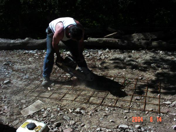
The engineer had designed the foundations as 300mm thick horizontal slabs, 1200mm wide, with 2 layers of A393 steel mesh. One of the foundations was to have a retaining wall on it, so it had to be tied into the wall. The wall would be two layers of 7N blocks, with more A393 mesh and concrete in the cavity. The steel came in 16 by 8 foot sheets. These sheets are heavy, and very difficult to handle due to the size. The farmer lent me his tractor to get the steel the 1/3 of a mile from the road.
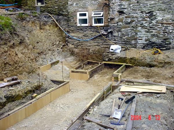
The architect plans required that we put piles of crushed stone into the foundation trenches. When the BCO examined the trenches he decided that the ground was suitable to use without the crushed stone, that saved a major bit of work, and suddenly gained us 150mm of headroom. I shuttered the trenches using a pile of 6x3 that had come out of an old barn we took down. In the far corner you can see that the formwork is less deep, this is because at this point we had reached the bedrock. The BCO agreed there was no need to remove bedrock to replace it with concrete.
I had employed a contractor to help with the concrete pour, after the issues with the excavator, I thought it wise. One of the guys came an helped me put the steel in.
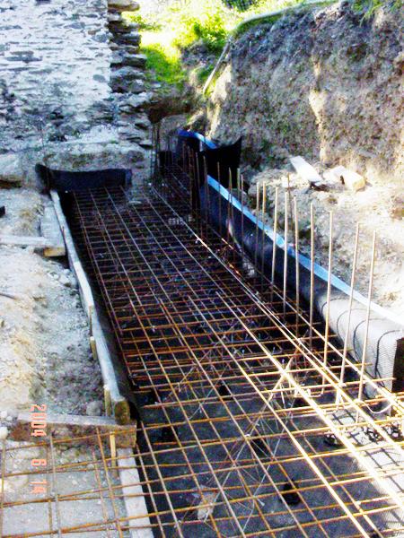
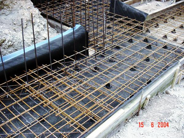
This is the retaining wall foundation trench with the steel in. You can see a very expensive plastic liner, to waterproof the bottom on the concrete, which would get joined into the retaining wall above. It was to later turn out that the BCO and the architect disagree about the waterproofing of the retaining wall, and this is not needed. The retaining wall gets 2 layers of waterproofing, one for the BCO, one for the architect.
You can also see steep poking up out of the formwork, this is to tie the wall into when we get that far. The steel overlaps are shown. Also you can see the steel poking out of the formwork, this is left out to join the second concrete pour onto the first.
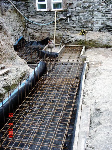
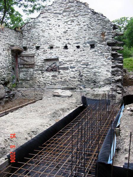
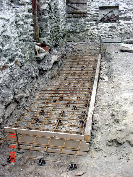
Finally a picture of the steelwork in place under the wall we undermined, roll on the concrete.
<